NFK Photo Eyepieces for BH2 Microscopes
Click here to see a description of NFK Photo Eyepieces
Click here to learn about applications of the NFK Photo Eyepieces.
Click here to for some NFK 1.67 stories.
Click here to see detailed specifications of the NFK photo eyepieces.
NFK Photo Eyepieces
Olympus NFK photo eyepieces fit within the inner bore of the 38mm dovetail on the trinocular head (and the PM-ADF eyepiece adapter) and picks up the unfinished intermediate image produced by LB objectives and projects a magnified real image, corrected for lateral chromatic aberration, onto the film or image sensor within the attached camera. The NFK photo eyepiece is a critical component of the Olympus LB optics family. In order to obtain aberration-free imaging, LB objectives must always be used with either an LB eyepiece (for direct viewing) or an NFK photo eyepiece (for photomicrography).
If you wish to attach a camera to the trinocular port of your BH2, you will need an NFK photo eyepiece (unless you somehow managed to find the elusive TVZ-M Zoom Video Lens, which integrates the compensation present in the NFK photo eyepieces). The corollary to this statement is “any third-party solution which purports to interface a camera to the BH2 that does not include an LB eyepiece or NFK photo eyepiece in the optical path will produce poor images with significant lateral chromatic aberration.”
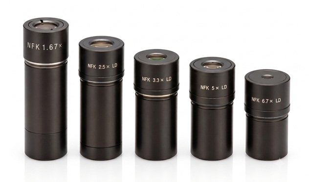
In addition to their use in photomicrography, NFK photo eyepieces are also used with the AH-MPS-W and AH-SPS-W projection screens, the BH2-DA drawing attachment, and the BH-WP wall projection prism.
NFK photo eyepieces were designed for use with the long-barrel objectives in the Olympus LB optics series and therefore include compensation for the lateral chromatic aberration that is present in the intermediate image produced by LB objectives. Because of this compensation, NFK photo eyepieces are not suitable for use with the older short barrel (36.65mm) objectives used on the BH and earlier microscopes, nor are they suitable for use with the newer UIS and UIS-2 infinity objectives on the BX and CX scopes.
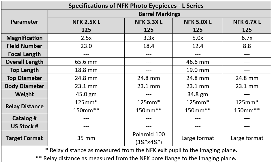
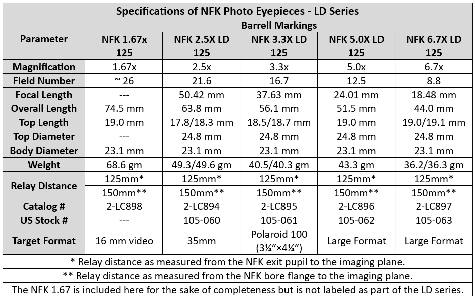
Olympus made two distinct versions of the NFK photo eyepieces: the early L series and the later LD series. The two were similar but not identical in their appearance, markings, and specifications. The early L series NFKs (which were included in the 1980 LB Objectives brochure and in the 1982 BHS/BHT brochure) are much less common than the later LD series.
Olympus specifies the NFK photo eyepieces as having a projection distance of 125 mm, which means that the image sensor must be placed 125mm from the exit pupil of the NFK photo eyepiece (the exit pupil is a few mm above the top glass). If you use an Olympus OM camera mounted onto a Photomicro L Adapter (or a Canon EOS DSLR with a suitable OM-EOS lens mount adapter), the image sensor will be at the correct distance to obtain parfocality with the viewing eyepieces.
If you’re making your own camera mount for the BH2, you should ignore the specified 125mm relay distance and work instead from the alternate specification. The distance between the ledge within the top bore of the 38mm dovetail on the trinocular head (on which the top section of the NFK photo eyepiece rests) and the image sensor within the attached camera must be 150mm.
The tables below show the specifications of the early L series and the later LD series of NFK photo eyepieces.
Application Notes for the NFK Photo Eyepieces
NFK photo eyepieces are not optically suitable for use as viewing eyepieces. Some versions of NFK photo eyepieces are so long that they would contact and damage the prisms if they were inserted into the ocular tubes of the binocular or trinocular heads.
The body of the NFK 1.67x is too long to be used with the SZ-PT phototube on an SZ4045 and likely other stereo microscopes.
The magnification of the NFK photo eyepiece should be chosen such that the projected image completely fills the image sensor of the attached camera, thereby producing images from the central region of the field of view of the eyepieces, with no vignetting.
In order to completely fill the image sensor, the diameter of the projected field should be slightly larger than the diagonal measurement of the image sensor. This ensures that the corners of the image sensor will be fully illuminated, thereby preventing vignetting. However, the diameter of the projected field should not be allowed to exceed the sensor diagonal dimension by too large of a margin, otherwise the field area captured by the camera will be significantly reduced as compared to the field of view through the eyepieces, which will be objectionable to many operators.
NFK eyepieces do not allow for the addition of eyepiece reticles by the users, but Olympus made a few that have a reticle permanently bonded in place.
The total magnification of the image projected onto the camera film or image sensor is determined by the equation:
PROJECTED MAGNIFICATION = OBJECTIVE MAGNIFICATION x NFK MAGNIFICATION x REDUCTION FACTOR.
The Photomicro L Adapter is optically neutral and therefore has no reduction factor (use 1.0x in the above equation). The MTV-3 C-Mount Adapter has a reduction factor of 0.3x. The large format film camera backs have a 3.0x reduction factor (reduction factors above 1.0x indicate magnification rather than reduction).
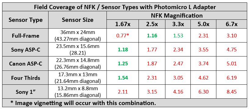
The table below shows the approximate field coverage of all permutations of common image sensor types and the available NFK magnifications. This table applies only when the camera has been attached using the Photomicro L Adapter (or third-party / DIY equivalent), and not for situations where a supplemental reduction optic is present within the optical path.
These numbers were calculated by dividing the diameter of the projected field (i.e., the FN of the objective multiplied by the NFK magnification) by the diagonal dimension of the rectangular image sensor. Any number less than 1.0 will not completely fill the image sensor, and will therefore produce vignetted images, while those greater than 1.0 will fill the sensor and not produce vignetting. The higher the ratio gets above 1.0, the narrower the resulting field of view becomes. For best results, try to stay slightly above 1.0.
The numbers shown in green are the acceptable choices based on field coverage, with the optimal choice shown in bold text. The numbers shown in red will either produce vignetting or an objectionably narrow field of view.
Of the three image sensor types considered here, the four thirds sensor is least suitable for usage with the Photomicro L Adapter, because of the relatively narrow field of view captured by four thirds cameras (the four thirds sensor is a much better fit when used with the MTV-3, rather than the Photomicro L Adapter, because of the 0.3x reduction factor of the MTV-3). In general, smaller sensors tend to be less suitable, while the larger sensors are suitable when used with the appropriate NFK magnification.
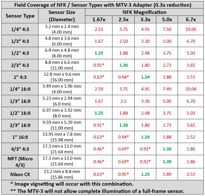
The table below shows the approximate field coverage of all permutations of the common sensor types used in C-mount cameras and the available NFK magnifications. This table applies only when the camera has been attached using the MTV-3 C-mount adapter (with 0.3x reduction factor), and not for situations where the 0.3x reduction factor is not present within the optical path.
These numbers were calculated by dividing the diameter of the projected field (i.e., the FN of the objective multiplied by 0.3 and by the NFK magnification) by the diagonal dimension of the image sensor. Any number less than 1.0 will not completely fill the image sensor, and will therefore produce vignetted images, while those greater than 1.0 will fill the sensor and not produce vignetting. The higher the ratio gets above 1.0, the narrower the resulting field of view becomes. For best results, try to stay slightly above 1.0.
The numbers shown in green are the acceptable choices based on field coverage, with the optimal choice shown in bold text. The numbers shown in red will either produce vignetting or an objectionably narrow field of view.
Of the various image sensor types considered here, the smaller sensors (which are widely prevalent in modern C-mount cameras) are not suitable for the BH2. Those sensors larger than 1/2” are suitable, when used with the appropriate NFK magnification.
If you end up using an NFK / image sensor combination which provides a significantly narrower field of view than the 10X eyepieces, you might try using 12.5x or even 15x eyepieces, to better match the field captured by the camera.
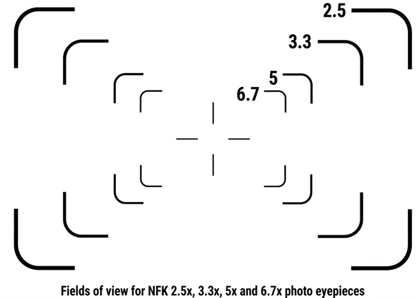
The NFK 2.5x photo eyepiece was originally intended for use with 35mm film cameras and is therefore perfectly suited for use with full-frame (24mm x 36mm) digital cameras. The NFK 2.5x photo eyepiece produces a rectangular sensor image that fits just within the circular field of view of the standard WHK 10x/20 L eyepieces. NFK 3.3x, 5.0x and 6.7x photo eyepieces can also be used with 35mm film or full frame digital cameras when higher magnification (with a correspondingly smaller field of view) is desired. The image below shows the finder reticle used in the various eyepieces intended for 35mm imaging. This reticle shows the field coverages of the various NFK magnification, as compared to the standard NFK 2.5.