
Polarized Light Microscopy
Click here to learn a little bit of wave theory.
Click here to learn about simple polarized microscopy.
Click here to learn how to add polarizing capability to a microscope.
Click here to learn about birefringence.
Click here to learn about phase retardation plates.
Click here to learn about quarter-wave retardation plates.
Click here to learn about full-wave retardation plates.
Click here to learn about Berek Compensators.
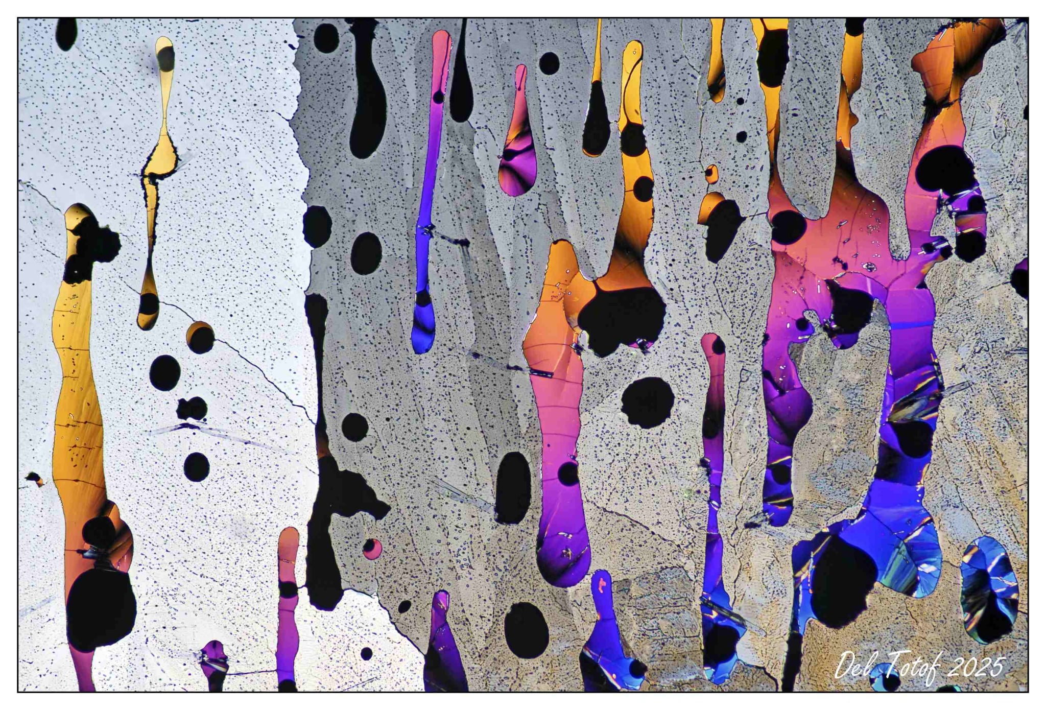
Sulfur, imaged with double polarization with 10x objective
(photo courtesy Del Totof of north of Quebec)
Click this image to open the full-resolution image in a separate window.
A Little Bit of Light Theory
Scottish physicist and mathematician James Clerk Maxwell developed his Classical Theory of Electromagnetic Radiation in the latter half of the nineteenth century. This work integrated Gauss’s Laws of Electricity and Magnetism, Faraday’s Law of Induction, and Ampere’s Law, into a unified theory which describes the behavior of electricity, magnetism, and light as a single phenomenon. Maxwell’s work is widely considered to be the second great unification of physics (the first being Isaac Newton’s unification of gravity with the behavior of celestial bodies). In 1884, Oliver Heaviside grouped the various expressions from Maxwell’s works into the elegant set of vector calculus equations known today as “Maxwell’s Equations”. Maxwell’s Equations are a set of four coupled partial-differential equations which fully describe the propagation of transverse electromagnetic waves through space.
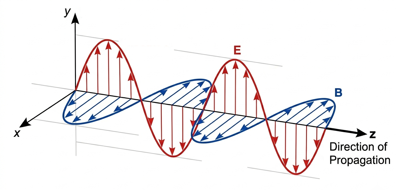
However, this is a BH2 website and not a college physics lecture, and since it has been a few years since I have taken any college electromagnetics or physics courses, we will skip the vector calculus here. Light propagates through space as transverse electromagnetic waves, in which there are cross-coupled B-field (magnetic) and E-field (electric) components, oriented perpendicular to each other and orthogonal to the axis of wave propagation. The image below shows a transverse electromagnetic wave with the B-field illustrated in blue and the E-field in red, and with the wave propagating in the Z-axis (towards increasing Z). Since convention dictates that the polarization of an electromagnetic wave is defined by the orientation of its E-field component, the wave in this image is horizontally polarized, because its E-field aligns with the horizontal X-axis.
Sunlight originates as thermal black-body radiation caused by nuclear fusion within the Sun’s core and hot plasma layers. The photons radiated by the Sun are independently emitted by countless trillions of atoms, at random times, each having no organized phase nor direction of oscillation. The earth’s atmosphere imparts a slight polarizing effect on the Sun’s light before it reaches the earth, but on the whole, the daylight we see is largely unpolarized. Additionally, most of the sources of light we use to illuminate our world outside of the daylight hours also produce unpolarized light. While some animals are capable of sensing light’s polarization and can use this information for navigation, humans are entirely blind to the polarization of light. But just because we cannot sense the polarization of light directly doesn’t mean that it cannot be useful to us. A perfect example of this is polarized light microscopy.
Simple Polarized Microscopy
The most basic application of polarized light to microscopy is referred to as “simple” polarizing microscopy. In this method, the specimen is illuminated with polarized light, which is created by sending unpolarized light through a filter which passes only light of a single polarization while blocking the rest. This polarized light then passes through the specimen, and in turn through a second polarizing filter (known as the analyzer), before being sent to the eyepieces.
If the two polarizers are situated such that their axes of transmission are parallel, the polarized light exiting the specimen passes through to the observer’s eyes and the viewer sees a normal brightfield image (although it will be somewhat darker, due to the loss of light caused by the first polarizer). This of course assumes that the specimen does not change the polarization of light as it passes through.
This next bit is where things get more interesting. If the second polarizer is rotated 90 degrees so that the axes of transmission of the two polarizers are perpendicular (a condition called “crossed polarizers”), none of the polarized light passing through the specimen will pass through the second polarizer (this condition is called “extinction”), and the observer will see a completely black field of view. This of course also assumes that the specimen does not change the polarization of the light passing through. But what happens if the specimen does change the light’s polarization, even if just a little bit, as it passes through?
When this happens, some portion of the light whose polarization has been changed by the specimen will pass through the second polarizer and become visible against a stark black background. Specifically, the birefringent specimen splits the incoming polarized light into two distinct wavefronts, which propagate through the specimen at different speeds and emerge from the sample as two waves that are out of phase to some degree or another. The amount of phase difference depends on the specific wavelength of the light and the thickness of the birefringent specimen. When these two wavefronts pass through the analyzer, it forces them to the same polarity, thereby allowing the two waves to interfere to form a visible image. Since white light contains light of all the visible wavelengths, the relative phase difference will be such that some colors will interfere constructively, while others will interfere destructively. It is this interference effect which produces the beautiful colors that we all know and love.
By changing the relative alignment of the two polarizers from parallel to perpendicular, the observer can change the image from a conventional brightfield presentation to that of a polarized image. By orienting the polarizers at some intermediate point between parallel and perpendicular, the resulting image will be a mixture of brightfield and polarizing.
So, what kinds of specimens affect the polarization of light? Materials that affect the polarization of light which passes through are called “birefringent” materials. Many crystals, fibers, plastics under stress, and even some biological tissues such as muscle fibers are birefringent, at least to some extent. The concept of birefringence is explained in some detail below, but for the purposes of simple polarization for the typical amateur microscopist, a detailed understanding of light, polarization, and birefringence is not strictly necessary. Just be aware that a birefringent material changes the polarization of light, and that in turn makes them show up when viewed under polarized light, often with spectacular colors.
Don’t fall for the misconception that simple polarized microscopy is only useful for making colorful images of crystals grown from chemicals randomly mixed by amateur microscopists. Sure, there is plenty of this going on out there, but simple polarization, while inherently a qualitive rather than quantitative technique, is commonly used for the detection of monosodium urate crystals in joint fluid (in the diagnosis of gout), or to detect calcium oxalate crystals in urine (for the treatment of kidney stones and gout).
How Can I Add Simple Polarizing Capability to My Microscope?
To add simple polarizing capabilities to just about any compound light microscope, you just need two linear polarizers of some sort. One of these polarizers is placed over the illumination source (typically beneath the condenser and just above the substage illuminator), to provide linearly polarized light with which to illuminate the specimen. The other polarizer is placed above the objective (typically just below the viewing head).
The actual filters which are used are not too critical here; inexpensive linearly polarized films are usually sufficient. But try to find a film that provides good extinction (i.e., exclusion of light) when the polarizers are arranged with their axes of transmission perpendicularly oriented to each other. For the one above the light source, you might consider spending a bit more and getting a good high-extinction glass polarizer, since you have quite a bit of latitude as to the physical dimensions of this lower filter. All that really matters here is that the light source be fully covered by the filter. The upper filter (the analyzer) is where the polarizing film may be the better option. Plastic film will allow you to trim the upper polarizer to the exact shape to fit below the viewing head. Once you have the two filters you will need, it’s time to set up for polarized viewing.
To set up for simple polarized viewing, remove the viewing head and drop the top polarizer (trimmed for proper fit) into the mounting recess for the viewing head, and reinstall the viewing head. Next, place the lower filter under the condenser and over the sub-stage light source. With the microscope configured in this way, if the bottom polarizer is rotated such that its axis of transmission aligns with that of the upper polarizer, the scope should work like a standard brightfield microscope, albeit with a 50% reduction in brightness due to the presence of the polarizers. If the bottom polarizer is rotated such that its axis of transmission is perpendicular to that of the upper polarizer (a condition called “crossed polarizers”), all visible light will be blocked from the eyepieces. Any birefringent specimen placed on the stage in this configuration will change the polarization of light as it passes through the specimen, allowing some portion of that light to travel through the upper polarizer and be visible to the observer.
With no slide on the stage, rotate the bottom polarizer until no light (or minimal light) can be seen through the eyepieces. This will be the orientation of maximum extinction (i.e., crossed polarizers), and this is where the magic happens. Place the specimen slide onto the stage and you are set up for polarized light observations. Any birefringent specimen, or birefringent sections of the specimen, will upset the polarization of light passing through the specimen, so that it will no longer be completely excluded by the upper polarizer, making the birefringent portions of the specimen visible against a dark background. If you still see a black image, it is likely because there is no birefringence in the specimen. Don’t forget that you can deviate the lower polarizer from its full-extinction orientation to “mix in” some of the brightfield image with the polarizing image, which can be quite useful to verify proper focus, composition, etc.
Birefringent Materials
Birefringence is the optical property of a material which causes a single ray of light entering the substance to split into two separate rays, which travel through the material at different speeds and angles. This happens when the molecular structure of the material imparts a different refractive index for different angles of incident polarization. Many crystals, fibers, plastics under stress, and even some biological materials are birefringent. A birefringent material has two axes of interest, which are perpendicular to each other. The axis which exhibits the lowest refractive index is known as the fast axis, since light propagates through the material fastest when its polarization aligns with this axis. Conversely, the axis which exhibits the highest refractive index is known as the slow axis, since light propagates through the material slowest when its polarization aligns with this axis.
If linearly polarized light is sent through a birefringent material with its polarization aligned parallel with either the fast or slow axis, it will emerge from the material with the same polarization, just phase delayed somewhat according to the thickness of the material and the propagation speed of the axis with which the polarized light was aligned. Things get a bit more interesting if the linearly polarized light is incident on the material such that both the fast and slow axes are illuminated by the same wave front. For instance, if linearly polarized light strikes the material at a 45° angle relative to both the fast and slow axes, both axes will see equal vector components of the illuminating light, which will then propagate through the material at two separate velocities, since there are two distinct refractive indices involved. Two equal-amplitude wavefronts will emerge from the material, with perpendicular polarizations which differ in phase. This phase difference is present because the two waves did not spend the same amount of time within the birefringent material, as a result of the different refractive indices that they experienced.
The emerging wavefront aligned with the slow axis will be phase retarded, as compared to the emerging wavefront aligned with the fast axis, due to the effective increase in path length it experienced while propagating through the slow axis of the material. The two emerging wavefronts will combine to form a circularly polarized wave, where the electric field vector rotates in a corkscrew-like fashion as the wave propagates through space. Circular polarization occurs in the special case where the fast and slow axes are equally illuminated by linearly polarized light. When both the fast and slow axes are illuminated at different relative amounts, the amplitude of the two rays exiting the material will be unequal, and will combine to form elliptically, rather than circularly polarized light.
What Is A Retardation Plate?
A waveplate (also known as a retardation plate) is an optically transparent plate made of a birefringent mineral or crystal (such as quartz, mica, calcite, or selenite), or other material, such as organic polymers sandwiched between two glass plates, installed in a metal or plastic support frame to provide protection for, and proper orientation of, the birefringent plate. The waveplate will be marked to identify the axes (slow and fast) of transmission, and the degree of retardation (typically expressed in nanometers) at some specific frequency. If linearly polarized light strikes the waveplate at a 45° angle relative to both the fast and slow axes, both axes will see an equal vector component of the illuminating light, which will then propagate through the waveplate as two separate wavefronts with different velocities, since there are two distinct refractive indices involved, and two equal-amplitude wavefronts will emerge from the crystal with mutually orthogonal polarizations that differ in phase.
The specific amount of phase difference at a given wavelength will depend upon the thickness of the crystal and on the type of the birefringent material from which the waveplate was made. Waveplate manufacturers carefully control the material selection, thickness, and orientation of the chosen material to produce specific amounts of retardation at a particular wavelength of light. For polarized microscopy applications, waveplates are usually constructed so that they provide their specified retardation with a green wavelength of approximately 540nm, since that is the middle of the visible spectrum. There are a few standard types of retardation plates used for polarized light microscopy, as described below.
Quarter-Wave Retardation Plates
A quarter-wave retardation plate is a waveplate constructed such that the two wavefronts emerging from the birefringent material differ in phase by one-quarter wavelength (i.e., 90°) when illuminated with a specific wavelength of linearly polarized light. Waveplates for polarizing microscopy are made to provide the specified retardation at green light (typically 540nm), since that is the middle of the visible spectrum. Since the polarization of the two emerging wavefronts will be perpendicular to each other, and since one will be phase retarded by one-quarter wavelength relative to the other, the emerging light will no longer be linearly polarized but will instead have elliptical or circular polarization. The quarter-wave retardation plate, which is used in polarizing microscopy to determine optical path differences of birefringent specimens as well as for the qualitative analysis of orthoscopic and conoscopic images, is inserted into the optical pathway with a 45° orientation of the fast and slow axes relative to the transmission axis of the illuminating polarizer, such that the fast and slow axes are equally illuminated by linearly polarized light from the polarizer. In this specific case of 45° illumination, the two emerging wavefronts will have equal amplitude and the resulting polarization will be circular. Some vector component of this circularly polarized light will pass through the linearly polarized analyzer to the eyepieces.
Full-Wave Retardation Plates
A full-wave retardation plate (also known as a first-order plate or a lambda plate) is a waveplate constructed such that the two wavefronts emerging from the birefringent material will differ in phase by one full wavelength when illuminated with a specific wavelength of linearly polarized light. Full-wave retardation plates for polarizing microscopy are made to provide 360° of phase retardation at green light (typically 540nm), since that is the center of the visible spectrum. A phase shift of one full wavelength means that the two emerging orthogonally polarized wavefronts will be in-phase, and because of this the emerging light will maintain the same linear polarization as that produced by the illumination polarizer, but only for this single specific wavelength. At all other wavelengths, the emerging wavefronts will experience some degree of relative phase shift which will produce some degree of elliptical polarization. The degree to which the emerging light is elliptically polarized depends upon how far the specific wavelength differs from wavelength at which the phase retardation is 360°.
In polarizing microscopy, the full-wave retardation plate is inserted into the optical pathway with a 45° orientation of the fast and slow axes relative to transmission axis of the illuminating polarizer, such that the fast and slow axes are equally illuminated by linearly polarized light. Without a birefringent specimen in the optical path, the green light emerging from the waveplate will remain linearly polarized and will have an orientation orthogonal to the transmission axis of the analyzer, thereby causing it to be completely absorbed by the cross-polarized analyzer and not visible to the observer. Since all other wavelengths will exhibit elliptical polarization to some degree or another, and since some vector component of all elliptically polarized waves will pass through the analyzer, all wavelengths other than the linearly polarized wavelength will be visible to the observer to some degree or another. Under these conditions the waveplate will appear an intense shade of red-violet (magenta), sometimes known as “sensitive tint”. This appearance gives rise to the full-wave retardation plate’s alternative names of “sensitive-tint plate”, or less commonly, “red-tint plate”. Full-wave retardation plates can be used to enhance contrast in weakly birefringent specimens, as well as to determine the optical sign of birefringent specimens or to estimate the optical path differences in birefringent specimens (ranging from a fraction of a wavelength to several wavelengths). They are widely used in mineralogy to aid in identification of minerals in thin sections of rocks and minerals.
When a birefringent specimen is placed into the optical pathway and aligned such that the fast and slow axes of the specimen are parallel to those of the full-wave retardation plate, the relative retardation produced by the birefringent specimen adds to that produced by the waveplate, shifting the point where the two orthogonal components are equal (and therefore linearly polarized) from green towards red. So, rather than the green light being blocked by the analyzer, the redder wavelengths tend to become blocked instead, while the green wavelengths become visible. This phenomenon shifts the perceived color of the light that travels through the specimen away from magenta towards cyan (which is a combination of green and blue light), with the degree to which this happens being a function of the amount of phase shift produced by the birefringent specimen.
If the birefringent specimen is rotated by 90° from the orientation described above, this will change the relationship between the slow and fast axes of the specimen and those of the full-wave retardation plate until they are now perpendicular, instead of parallel. In this case, the relative retardation produced by the birefringent specimen subtracts from that produced by the waveplate, shifting the point where the two orthogonal components are equal (and therefore linearly polarized) from green towards blue. So, rather than green light being blocked by the analyzer, the bluer wavelengths tend to become blocked while once again the green wavelengths become visible. This shifts the perceived color of the light that travels through the specimen away from magenta towards yellow (which is a combination of red and green light), with the degree to which this happens being a function of the amount of phase shift produced by the birefringent specimen.
The Berek Compensator
The Berek compensator (also known as a “Berek Tunable Retarder” or “Berek Waveplate”) was named after its inventor, German physicist Max Berek. Berek’s device is a simple, tunable retardation plate which is commonly used in polarized light microscopy to measure the wave retardation of birefringent specimens, such as crystals, fibers, or minerals. The Berek compensator is essentially a birefringent plate which can be tilted relative to the incident beam via a rotating dial of some sort. Markings on the dial can be used along with supplied tuning graphs to allow the operator to correlate the position of the knob to the phase retardation at various wavelengths. The Berek compensator consists of a single uniaxial birefringent crystal, with its optical axis perpendicular to the parallel faces. Under conditions of normal incidence, there is no phase retardation, but a variable degree of retardation can be introduced by tilting the angle of the plate with respect to the incident beam (the phase retardation increases proportionally to the square of the angle of tilt). While this tilting mechanism allows the Berek Compensator to function as a tunable, true zero-order waveplate, the tilt of the birefringent plate introduces an undesired beam offset which varies with the retardation setting (but this issue can be tolerated in many situations). One method to minimize the variable beam offset is to use a high birefringence crystal of minimal thickness. Berek compensators are used where variable phase retardation is required and true zero-order performance is desirable, when working with a large optical bandwidth, such as polarized light microscopy. Berek compensators can often replace the more expensive Babinet–Soleil compensators in cases where the Berek’s variable beam offset can be tolerated.